Giving sequence to the series of the fuel injection posts, here is a pseudo-code of the system. I decided not include the full working code, because every application will be different and will require different solutions and it will result in a code that is radically different. So, this is to read, understand, and from it, I'm sure everyone can replicate the system.
First of all I'll assume you have already read the first part, otherwise, this thing ll not make any sense....
Declaration of necessary things:
First as in every arduino sketch you have to describe all the variables you'll need.
Gone with the basic variables, I'll focus on the stuff I really struggled to make work.
First is a fuel injection map (that thing everyone like to mess around on their cars)
and a ignition map (the storage of these variables goes the same way, so just use the example of the ignition timing here:
const byte avanco[16][11] = {
{-5, -5, -5, -5, -5, -5, -5, -5, -5, -5, -5}, //0 - coloquei retardo para ligar o motor
{ 8, 6, 5, 2, 0, 0, 3, 10, 15, 14, 9}, //500rpm - marcha lenta
{23, 22, 20, 18, 15, 15, 18, 20, 19, 16, 11}, //1000rpm
{27, 27, 27, 27, 26, 23, 23, 24, 21, 18, 13}, //1500rpm
{30, 30, 30, 30, 30, 30, 30, 27, 24, 21, 16}, //2000rpm
{38, 38, 38, 38, 38, 38, 38, 35, 32, 29, 24}, //2500rpm index5
{45, 45, 45, 45, 45, 45, 45, 42, 39, 36, 31}, //3000rpm
{46, 46, 46, 46, 46, 46, 46, 43, 40, 37, 32}, //3500rpm
{46, 46, 46, 46, 46, 46, 46, 43, 40, 37, 32}, //4000rpm
{46, 46, 46, 46, 46, 46, 46, 43, 40, 37, 32}, //4500rpm
{46, 46, 46, 46, 46, 46, 46, 43, 40, 37, 32}, //5000rpm index10
{46, 46, 46, 46, 46, 46, 46, 43, 40, 37, 32}, //5500rpm
{ 5, 5, 5, 5, 5, 5, 5, 5, 5, 5, 5}, //6000rpm
{ 5, 5, 5, 5, 5, 5, 5, 5, 5, 5, 5}, //6500rpm
{ 5, 5, 5, 5, 5, 5, 5, 5, 5, 5, 5}, //7000rpm
{ 5, 5, 5, 5, 5, 5, 5, 5, 5, 5, 5}};//7500rpm index15
//0 10 20 30 40 50 60 70 80 90 100 //kPa
this is an array of arrays witch can be accessed, depending of the condition the engine is.
each collum represents a specific engine RPM and each row, an engine load
on the setup:
void setup()
{
attachInterrupt(1, RPM, FALLING); // 1 pino3, chama a funcao RPM, no FALLING edge
TCCR1A = 0;
TCCR1B = 0;
TCCR1B |= (1 << CS12); // / -so o bit CS12-preescaler 256 (vide tabela AVR)
//esse timer estoura com 1.04s
TCCR1B |= (1 << ICNC1); //seta o Input Capture Noise Canceler faz um buffer de 4 clocks para //mudar de estado
TIMSK1 |= (1 << OCIE1A); // enable timer 1 compare interrupt A
TIMSK1 |= (1 << OCIE1B); // enable timer 1 compare interrupt B
TIMSK1 |= (1 << OCIE1C); // enable timer 1 compare interrupt C
TIMSK1 |= (1 << TOIE1); // enable timer overflow interrupt
}
On the setup, you should assign every pin and etc, but the main thing is to setup the interruptions and timer1 configuration.
The main code:
Here is a part that seem to not make sense..... anyway, that's the way I did:
void loop()
{
pressao = analogRead(pin_pressao);
calculo1();
}
Yeah.... the mais code is just it.... read all sensors and call all the calculation functions.
why?
Because this way is easier not to just add another function, or another sensor reading, but to coordinate the timing of each operation.
In my case, the calculation necessary is so heavy for the arduino, it take almost 3ms to operate. It may seem not like much, but an engine at 12000 rpm give me just 5ms each turn.
To compensate for that, I broke the calculation into 2 functions: "calculo1" and "calculo2". Since the engine takes 2 turns to complete a cycle, I can run part of the math on every turn, and read the sensors at the time I decide it's the best.
The Interruptions:
Here's the crucial part. Since the arduino can be doing all kinds of crazy math while the engine rev, it's important that the code keep track of what's going on, and do the actuation at the precise moment.
void RPM()
{
interrupts();
if (volta == 1){
t_ciclo = TCNT1;
TCNT1 = 0;
if (Corte == 0){
digitalWrite (bico1, HIGH);
}
OCR1B = T_Injecao_Total_int;
volta=2;
}else if(volta==2){
t_volta = TCNT1;
volta=1;
}
This interruption comes from the TDC sensor. Instead of using a degree wheel or any fancy device, the system (at least for the kart engine, the six cylinder uses a slightly different strategy) uses just the TDC sensor.
The system marks each of the engines turn, and triggers the fuel injector (bico1) just once per CYCLE. The injector start spraying the fuel on TDC and the reason for this is just to simplify the code and because the arduino has just 2 time comparators to use, and one of them is used to close the injector when time reaches the value calculated (OCR1B) the variable "Corte" is there just for cut-off strategies.
The TCNT1 is the value of timer1 at any given moment, and it is reseted every cicle.
ISR(TIMER1_COMPB_vect) // timer compare interrupt service routine
{
interrup1B();
}
void interrup1B(){
interrupts();
digitalWrite (bico1, LOW);
}
ISR(TIMER1_COMPA_vect) // timer compare interrupt service routine
{
interrup1A();
}
void interrup1A(){// interrupcao para controlar a bobina de ignicao
interrupts();
if (bob == LOW){
digitalWrite (bobina, HIGH); //liga a bobina
bob = HIGH; //indica que a bobina foi ligada
OCR1A = TCNT1 + dw_t; //seta essa interrupcao novamente para daqui o tempo de carga
}else{
digitalWrite (bobina, LOW); //efetivamente o disparo da bobina!
bob = LOW; //indica que a bobina foi desligada e nao faz mais nada...
}
}
Here are the interrupts that control the closing time of the injector, and turns the ignition coil on and off. These interrupts works as is. The only thing to notice here is that the interruption A that control the ignition, turns the ignition ON, and reassigns itself to turn OFF, this works because the coil need to be on for a fixed amount of time depending of the battery voltage.
Another thing that need attention is the fact that every interruption just call a function, and the first thing of the function is to turn the interruption on, which make possible to run an interruption inside an interruption (totally INCEPTION!)
Calculations:
On another post....
quarta-feira, 9 de março de 2016
quinta-feira, 3 de março de 2016


domingo, 7 de fevereiro de 2016
Arduino ECU
Today the post is to talk about the electronic fuel injection system of the Opala. This post is in english not to show off my english skills (probably is the other way around), but to make the post accessible to a wider variety of people that build projects with the arduino boards. To simplify things, and knowing the system is the same. I will speak of the electronic fuel injection of my kart, and how to make an electronic fuel injection from scratch!
To get the electronic injection system, the first thing you need is a computer, or in the case a miniaturized computer.I choose the arduino for simplicity of code (remember I'm MECHANICAL engineer, not a programmer especialist, despite having work experience with it), USB interface for easy connection, and a reasonable number of inputs and outputs. , how to connect the most different things to precise injection . Another reason to choose the Arduino is the large developer community on the internet that, like me in this post share their projects and thereby help solve the problem of others.
Then you need to define what will be necessary for the operation of the injection. Let's stick to the basic:
-Control the fuel, using the injector (or several)
-Control the ignition coil (or several) (the first version of the kart injection was so simple that wore the original CDI )
-Read Engine load (MAF, MAP or TPS)
-read The engine speed and know your PMS (hall sensor, distributor, tone wheel, whatever)

This makes it possible to start the engine.
Now it's time to put it all together.
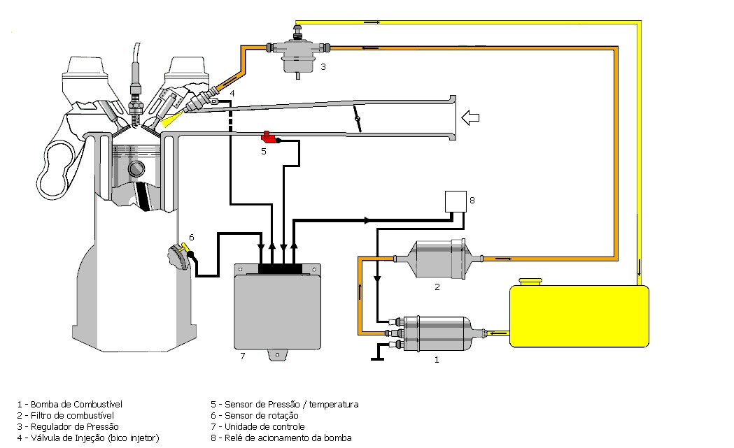
Here I will give the example of my kart, everything was used and how it was used. First you need to make a way to the fuel reach the engine, so, you need a fuel pump, a fuel pressure regulator, and a fuel injector, and of couse, all the hoses that connects these parts.
To interface the sensors and actuators with the processor, it is necessary a circuit board that lessens noise, attenuates or amplifies the signals, in other words, let the signals ready to be read by the processor, and allow the actuator to work properly.
So first you have to know the "language" spoken by each piece.
-To Read the motor load, used a MAP sensor, Bosch, code 0261230030. It tells the absolute pressure with a value of 0-5v linearly from 0 to 115KPa (simplified, look for the correct calibration curve).
-for The rotation in the case of CG engine I use in the kart, I simply used the original rotation sensor that comes with the engine of the original bike. It is an inductive type sensor, and sends a voltage pulse (+ - 30v) every time a tooth (in case one coupled to the crankshaft)passes by it. When he is in positive voltage maximum, this means that the crankshaft is at 15º before TDC (top dead center) (it came like that, no particular reason).
-Fuel injector: I used a high impedance Bosch, code: 0280155821. This nozzle has a flow rate of 200cm3 / min (can not remember now).
-Bobina: I used a coil of Fiat Uno (one of two outputs) connecting one of the spark plug wires directly on the motor housing, and the other in the spark plug itself (I will not explain why it now, just believe me ... it works).
To install the injection engine, had also to develop an intake manifold that allows the pressure sensor to be installed in the intake duct for him to read the motor load, it should also contain a throttle plate, and hold and drive nozzle to make a good mix air-fuel.
 How to do this connect with the Arduino? Well, I knew what I needed, but how to achieve is where the problem was. This has been solved thanks to my friend Arao, from Eletrônica na Bancada blog. Arao is a great friend and knows A LOT of electronics.
Here is a compilation of the circuits the board uses:

 The lower image show the crankshaft position sensor circuit, the output for that is point 12. Every circuit is labeled in portuguese (If you did'n notice, I'm Brazilian, and everything from this project was idealized, made, programmed, and built in Brazil, so just use google tradutor :) ).
Next time: the code.
To get the electronic injection system, the first thing you need is a computer, or in the case a miniaturized computer.I choose the arduino for simplicity of code (remember I'm MECHANICAL engineer, not a programmer especialist, despite having work experience with it), USB interface for easy connection, and a reasonable number of inputs and outputs. , how to connect the most different things to precise injection . Another reason to choose the Arduino is the large developer community on the internet that, like me in this post share their projects and thereby help solve the problem of others.
Then you need to define what will be necessary for the operation of the injection. Let's stick to the basic:
-Control the fuel, using the injector (or several)
-Control the ignition coil (or several) (the first version of the kart injection was so simple that wore the original CDI )
-Read Engine load (MAF, MAP or TPS)
-read The engine speed and know your PMS (hall sensor, distributor, tone wheel, whatever)
This makes it possible to start the engine.
Now it's time to put it all together.
Here I will give the example of my kart, everything was used and how it was used. First you need to make a way to the fuel reach the engine, so, you need a fuel pump, a fuel pressure regulator, and a fuel injector, and of couse, all the hoses that connects these parts.
To interface the sensors and actuators with the processor, it is necessary a circuit board that lessens noise, attenuates or amplifies the signals, in other words, let the signals ready to be read by the processor, and allow the actuator to work properly.
So first you have to know the "language" spoken by each piece.
-To Read the motor load, used a MAP sensor, Bosch, code 0261230030. It tells the absolute pressure with a value of 0-5v linearly from 0 to 115KPa (simplified, look for the correct calibration curve).
-for The rotation in the case of CG engine I use in the kart, I simply used the original rotation sensor that comes with the engine of the original bike. It is an inductive type sensor, and sends a voltage pulse (+ - 30v) every time a tooth (in case one coupled to the crankshaft)passes by it. When he is in positive voltage maximum, this means that the crankshaft is at 15º before TDC (top dead center) (it came like that, no particular reason).
-Fuel injector: I used a high impedance Bosch, code: 0280155821. This nozzle has a flow rate of 200cm3 / min (can not remember now).
-Bobina: I used a coil of Fiat Uno (one of two outputs) connecting one of the spark plug wires directly on the motor housing, and the other in the spark plug itself (I will not explain why it now, just believe me ... it works).
To install the injection engine, had also to develop an intake manifold that allows the pressure sensor to be installed in the intake duct for him to read the motor load, it should also contain a throttle plate, and hold and drive nozzle to make a good mix air-fuel.

Here is a compilation of the circuits the board uses:


Next time: the code.
quarta-feira, 6 de janeiro de 2016
Acelerando o TREM
Seguindo os posts sobre dinâmica veicular, vou continuar postando aqui como esse negócio funciona (de maneira bem básica).
Sem mais enrolação, vamos ao que interessa:
Quando um carro acelera, freia ou faz curva, o efeito da massa atua alterando momentaneamente as forças que atuam nas rodas, isso foi explicado no post sobre o CG. Como comentei antes, a massa do carro apenas reage à força que os pneus fizeram para acelera-lo (aceleração longitudinal e/ou lateral). Mas a questão nesse post é analisar de que maneira essas forças atuam sobre o chassi.
Como a roda não é presa de maneira rígida ao chassi (então não estamos falando de um kart) a força que as rodas fazem para mover o carro devem percorrer a suspensão para chegar ao chassi e faze-lo ir para onde se quer.
Então para descobrir como o carro vai atuar ao sofrer uma aceleração basta analisar a geometria da suspensão do carro. O grande lance está em analisar o ponto de reação da suspensão, que pode ser tanto um ponto imaginário (caso de suspensões do tipo multilink, ou um four-link) ou um ponto real mesmo (caso dos tipos swing axle ou trailing arm), basta observar o esquema na imagem.
 Então para saber o que acontece com o chassi, basta ter em mente que a força do motor será descarregada no chassi através desse ponto. Há também que se levar em conta que a força não age na horizontal, ou seja, ela não “empurra” simplesmente o carro para frente, a força vem das rodas que estão em contato com o chão.
Aqui vale uma nota: quando o torque das rodas é gerado dentro da suspensão (caso dos freios outboard que são a maioria esmagadora, ou do eixo vivo (traseira do opala)) a força que vem das rodas para o chassi, fica no sentido do ponto de contato da roda com o chão, em direção ao ponto de reação da suspensão.
Já no caso onde o torque é gerado fora da suspensão (caso dos freios inboard, e no caso da tração, todos os casos onde o diferencial é preso no chassi), a força vai do centro da roda em direção ao ponto de reação da suspensão.
Quem esta lendo já deve ter percebido que o vetor da força raramente esta na horizontal, o que implica que parte da força esta realmente empurrando o carro para frente (horizontal) e outra, esta atuando na vertical.
Essa resultante vertical afeta a maneira como o chassi vai se comportar durante a aceleração (frenagem também). Dependendo da quantidade de força vertical aplicada, o carro pode tanto comprimir, estender, ou manter imóvel a suspensão de tração.
Vale lembrar que essas considerações só funcionam no eixo de tração. Então, pra um carro de tração traseira, a dianteira vai SEMPRE erguer, e no caso de um tração dianteira, a traseira vai SEMPRE abaixar. Isso por causa da transferência de carga.
Com isso é possível ajustar a suspensão do carro a fim de obter a melhor tração. Isso mostra de novo a importância de se saber a posição do centro de gravidade (centro de massas) do carro, ja que toda reação do chassi se baseia nessa posição e todos os cálculos dependem dessa informação.
Sem mais enrolação, vamos ao que interessa:
Quando um carro acelera, freia ou faz curva, o efeito da massa atua alterando momentaneamente as forças que atuam nas rodas, isso foi explicado no post sobre o CG. Como comentei antes, a massa do carro apenas reage à força que os pneus fizeram para acelera-lo (aceleração longitudinal e/ou lateral). Mas a questão nesse post é analisar de que maneira essas forças atuam sobre o chassi.
Como a roda não é presa de maneira rígida ao chassi (então não estamos falando de um kart) a força que as rodas fazem para mover o carro devem percorrer a suspensão para chegar ao chassi e faze-lo ir para onde se quer.
Então para descobrir como o carro vai atuar ao sofrer uma aceleração basta analisar a geometria da suspensão do carro. O grande lance está em analisar o ponto de reação da suspensão, que pode ser tanto um ponto imaginário (caso de suspensões do tipo multilink, ou um four-link) ou um ponto real mesmo (caso dos tipos swing axle ou trailing arm), basta observar o esquema na imagem.
Então para saber o que acontece com o chassi, basta ter em mente que a força do motor será descarregada no chassi através desse ponto. Há também que se levar em conta que a força não age na horizontal, ou seja, ela não “empurra” simplesmente o carro para frente, a força vem das rodas que estão em contato com o chão.Aqui vale uma nota: quando o torque das rodas é gerado dentro da suspensão (caso dos freios outboard que são a maioria esmagadora, ou do eixo vivo (traseira do opala)) a força que vem das rodas para o chassi, fica no sentido do ponto de contato da roda com o chão, em direção ao ponto de reação da suspensão.
Já no caso onde o torque é gerado fora da suspensão (caso dos freios inboard, e no caso da tração, todos os casos onde o diferencial é preso no chassi), a força vai do centro da roda em direção ao ponto de reação da suspensão.
Quem esta lendo já deve ter percebido que o vetor da força raramente esta na horizontal, o que implica que parte da força esta realmente empurrando o carro para frente (horizontal) e outra, esta atuando na vertical.
Essa resultante vertical afeta a maneira como o chassi vai se comportar durante a aceleração (frenagem também). Dependendo da quantidade de força vertical aplicada, o carro pode tanto comprimir, estender, ou manter imóvel a suspensão de tração.
Vale lembrar que essas considerações só funcionam no eixo de tração. Então, pra um carro de tração traseira, a dianteira vai SEMPRE erguer, e no caso de um tração dianteira, a traseira vai SEMPRE abaixar. Isso por causa da transferência de carga.
Com isso é possível ajustar a suspensão do carro a fim de obter a melhor tração. Isso mostra de novo a importância de se saber a posição do centro de gravidade (centro de massas) do carro, ja que toda reação do chassi se baseia nessa posição e todos os cálculos dependem dessa informação.
Assinar:
Postagens (Atom)